How to Install Solar Mounting Rails: A Field Guide for Installers
The rail is the structural backbone of the array. This sequence walks installers through substrate checks, rail layout, fastening order, roof-specific adjustments, and the final verification that prevents module stress.
Install solar mounting rails in the right order: verify the roof structure, set bracket positions, run the rails, align the plane, then torque. Skip the preparation or fasten out of sequence, and the array carries stress into the modules. This guide covers the rail installation step only—not system design, not module wiring, not roof structural engineering. Once the brackets or hooks are fixed, the rail is the next load path. Treat it as structural work.
Key Takeaways
- Rail installation is a sequenced structural task, not a fit-and-forget step.
- Pre-installation checks on rafters, brackets, and roof condition prevent most alignment and fastener failures.
- Final verification of straightness, spacing, splice integrity, and fastener seating must happen before modules are clamped.
What the rail installation step actually covers
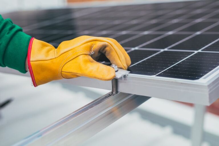
Solar mounting rails—also called channels—carry the PV modules in rows. They are fixed to brackets or hooks that are anchored to the roof structure. The installer’s job at this stage is to create a straight, parallel, correctly spaced plane for module clamps. This article assumes the roof-mounting choice has already been made; roof vs ground mounting systems follow a different structural path. It also assumes brackets, hooks or stanchions are specified and installed according to the roof type. Rail installation begins after those supports are secured and verified.
Pre-installation checks before any rail is fixed
Before a rail touches a bracket, verify the rafter or truss locations and spacing. Mark every fixing point on the roof surface and check it against the bracket positions. If a bracket misses a rafter or lands on a purlin edge, the rail cannot be safely loaded. Confirm the roof structure is sound: no cracked tiles, corroded metal, loose battens, or soft decking under the bracket line. Confirm the bracket or hook type matches the roof material—tile, corrugated metal, shingle, or trapezoidal sheet. Check tool readiness: calibrated torque wrench, appropriate bits, string line, laser or chalk line, and personal fall protection. Do not start rail installation in wet, windy, or storm conditions.
For pitched roofs, the bracket-to-rafter connection is the most common failure point. Review the practical checks before fixing rails to rafters before you proceed. A rail is only as sound as the bracket that carries it.
Parts and hardware needed for rail installation
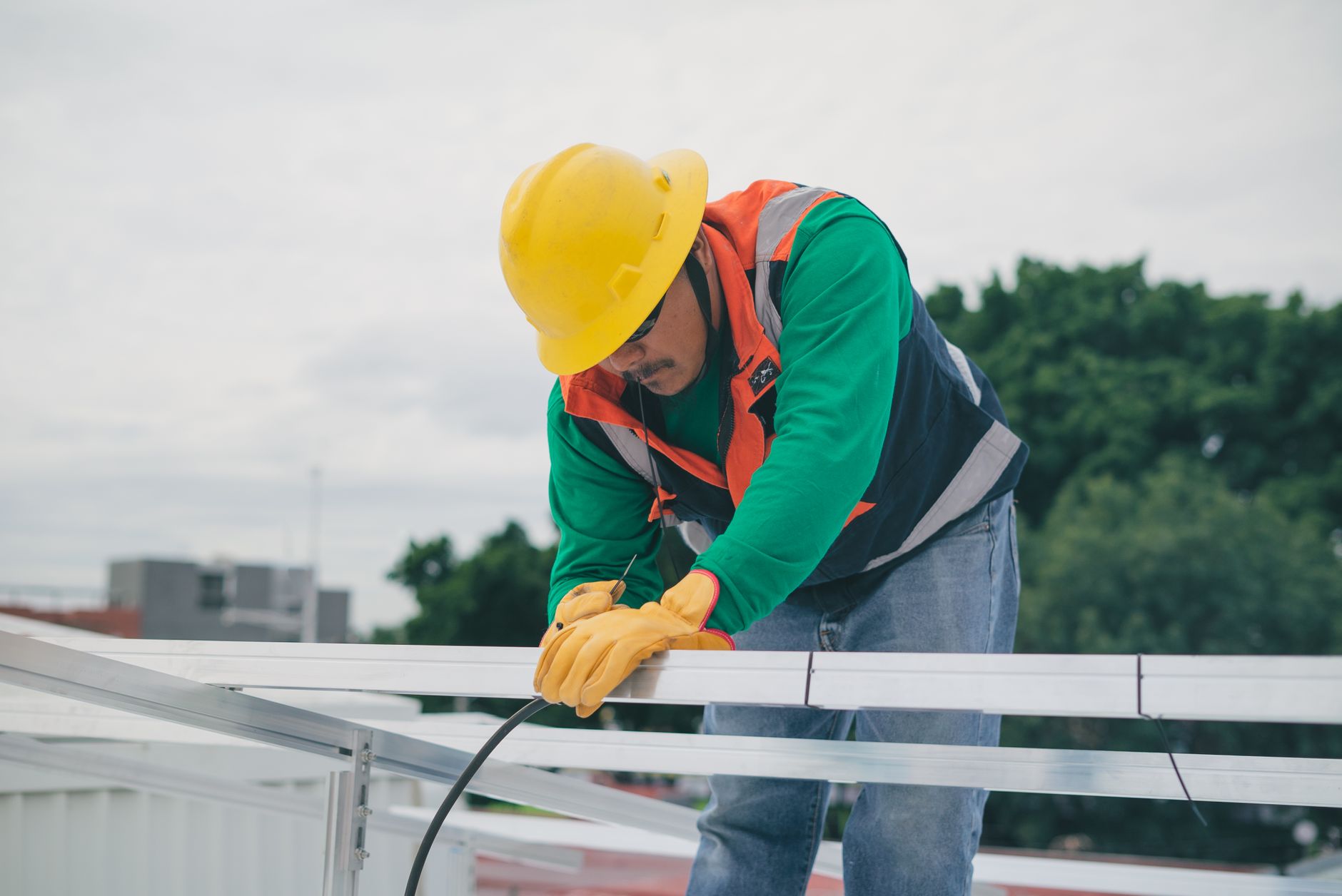
Gather the full set before anyone goes up the ladder. Generic requirements include: rails or channels cut to length with splice kits where runs exceed single-rail length; mounting brackets, hooks, or L-feet matched to the roof substrate; mid and end clamps for the modules that will sit on the rails; fasteners appropriate to the roof substrate—wood screws for rafters, self-drilling screws for purlins, or bolt sets for concrete; and the tools needed for marking, drilling, aligning, and torqueing. If rails must join mid-run, use the correct splice connector and keep the joint away from a module clamping point.
When the hardware list is clear, source the generic parts from a dependable solar mounting components range so every piece matches the rail profile and the roof substrate.
Step-by-step rail installation sequence
1. Mark the rail layout on the roof plane. Use the project’s string spacing or rail spacing table. Snap chalk lines or set a string line along the first and last rail positions. Check that the lines are parallel and square to the roof edge or ridge, not just visually parallel to the nearest tile course.
2. Set bracket or hook positions. Transfer the rail line to the bracket locations and align each bracket to a rafter, purlin, or approved structural member. Drill pilot holes only where the substrate requires them; do not pre-drill where self-drilling fasteners are specified. Set brackets loosely at first—enough to hold position, not enough to prevent adjustment.
3. Lay rails into brackets and adjust spacing. Place the first rail in its brackets or hooks. Use a spacer or measuring rule to set the distance to the next rail, based on the module’s mounting hole spacing and clamp design. Check the rail-to-rail dimension at both ends and the middle. Adjust brackets before tightening.
4. Fasten rails to brackets in a controlled sequence. Secure one end of the first rail, then move to the other end and align the rail to the layout line before securing. Do not apply final torque until the rail is straight. Work along the rail, tightening each bracket lightly. Avoid over-torquing before alignment check—deforming the rail channel at one point can lock in a bow.
5. Splice rail sections where runs exceed single-rail length. Install the splice connector first, slide the next rail section into place, and align the joint. Fasten the splice hardware before torqueing the rail-to-bracket fasteners. The splice must sit flush, with no step or gap between rail ends.
6. Check straightness and parallel alignment before final torque. Pull a string line along each rail. Look for sag, twist, or wave. If the rail follows the roof surface unevenly, adjust the bracket height or add shims only where the mounting system allows. Then perform final torque in a crossing pattern from the middle outward, or as specified by the bracket manufacturer.
Roof-type-specific rail installation notes
Pitched shingle and metal roofs
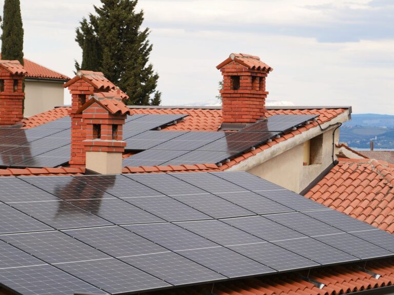
On pitched shingle roofs, the rail load passes through the bracket into the rafter. Every bracket must hit structural wood, not just decking. Use flashing where the bracket penetrates the roof surface and seal it in the correct order: under the upper shingle course and over the lower course, so water sheds away. On standing seam or corrugated metal roofs, the mounting bracket normally clamps to the seam or screws into the purlin. Align rails to the purlin spacing, not just the seam lines, and avoid fastening into unsupported ribs. A rail that spans between purlins without support will flex and transfer stress to the module glass.
Tile roofs
Tile roofs introduce a different failure mode: the tile hook or bracket can slip down the slope, especially on steep pitches. Standard tile hooks often rely on a single fixed point and may not resist downhill movement once rail weight and thermal cycling act on them. Before rails go on, verify that the hook is seated against the batten or rafter, not resting on the tile surface alone. Check the anti-slip detail and the hook’s load path. For steep roofs, review the tile hooks on steep roofs failure mode. Rails on tile roofs should run parallel to the ridge and be checked for any tendency to shift before modules are clamped.
Iron and steel roofs in tropical climates
On iron and steel roofs, rail installation in humid or coastal tropical conditions demands extra attention at every fastener point. Pre-drilling may be required for thicker structural steel; self-drilling screws work on thin sheet but can strip if over-torqued. Use a calibrated torque setting and a depth control to avoid crushing the rail channel or the roof sheet. Leave room for thermal expansion at long rail runs; fixed points at both ends can cause rails to bow in hot sun. For installers working on cement roof solar installation in the Philippines, the substrate checks change—rails there usually anchor to concrete beams or embedded fasteners, not sheet iron. In all tropical steel roofs, inspect fastener contact areas for moisture traps and specify isolation washers where dissimilar metals meet.
Common installation failures and how to prevent them
Most rail-related callbacks come from a small set of field errors. Recognize them early and fix them before modules hide the rail.
- Misaligned rails causing module stress: check string lines at both ends and mid-span before final torque.
- Insufficient fastener embedment: confirm the fastener reaches the structural member, not just sheathing or insulation.
- Skipped splice connections: every rail joint must use the correct splice hardware and sit flush.
- Over-torqued fasteners deforming rail channels: stop at the point where the channel edge distorts; back off and re-seat.
- Tile hooks that slip on steep pitches: use anti-slip details and verify hook seating against the structural member.
- Rails installed before bracket alignment is confirmed: set and adjust brackets before bringing rails onto the roof plane.
Post-installation verification checklist
Before any module is placed on the rails, walk the array with this checklist. Completion of each item is the signal to start clamping modules. If any item fails, correct it before continuing.
- Rail straightness: pull a string line along each rail and check for gaps or waves.
- Spacing tolerance: measure between parallel rails at both ends and at mid-span; compare to the module mounting hole tolerance.
- Fastener tightness: every rail-to-bracket fastener is seated and torqued; no loose brackets, no stripped threads.
- Splice integrity: every rail joint is flush, with no step, gap, or movement.
- Bracket/hook seating: every support is fully engaged with the structural member; no bracket is floating or bearing on tile surface only.
- Visual alignment: the rail plane looks uniform across the roof; the rails are parallel to each other and to the roofline or reference line.
- Clean work surface: no debris, loose screws, or cut swarf left where modules or wires will sit.
Rail installation is complete only when the plane is straight, the fasteners are seated, and every splice is flush. That verification step is not optional—it is the last chance to correct an alignment or torque issue before module clamps lock the array together. Move to module installation only after the checklist passes.